Friday 16 February 2018

how resistor work | techmodernize

how resistor work? 

What is resistor?
The resistor is an electronic component restricts or limit the flow of current and divides the voltage in an electronic circuit. It is one of the most important passive components of an electronic industry because, without these components, active devices cannot process the electrical signals. Its main purpose is to provide a precise quantity of electrical resistance
Resistor image

Resistors Basics:

Resistors mainly added to those circuits where they complement the active components like integrated circuits, op amp, microcontrollers etc. To form resistor networks it can be connected in various parallel and series combination.

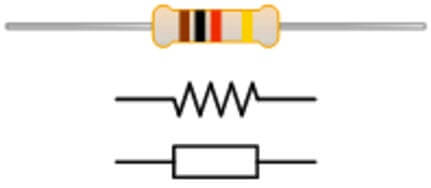
(i) Resistor Symbol:

resistor symbol image
It is a two terminal device have one connection on each of its sides. Two common resistor symbols are shown in given figure; one is in American style (zig zag line) and other is international style. Resistor values displayed in ohms is critical for both evaluating and actually constructing the circuit. Each resistor in a circuit should have unique name/number. In a circuit diagram, the SI prefix symbol for a particular value in European countries is written as 2K4 which indicates  a resistor value of 2.4KΩ etc.

(ii) Resistor working:

As per ohm’s law, the behaviour of an ideal resistor is explained by the given equation:
V= I * R 
This law states that the ratio of the voltage and the current is equal to the constant i.e. resistance known as the constant of proportionality. For example, if a 200-ohm resistance is attached across the terminals of the 10V battery, then a current of 10/ 200 = 0.05 Ampere flows through that resistor. In alternating current circuits, practical resistors also have some inductance and capacitance. These are generally made up of metal wire or carbon and engineered to maintain a stable resistance value over a wide range of environmental conditions. In a working circuit, they do not produce light but they do produce heat as the electric power dissipated by them.

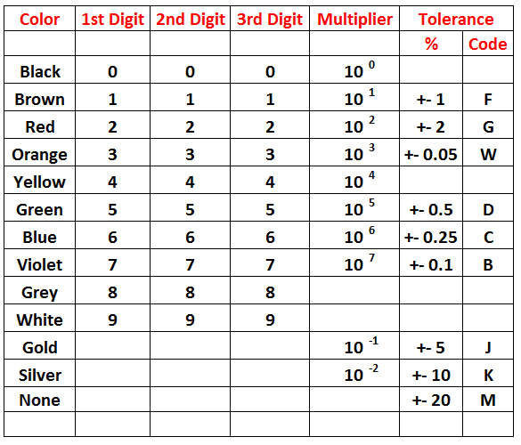
Resistor Color Code:

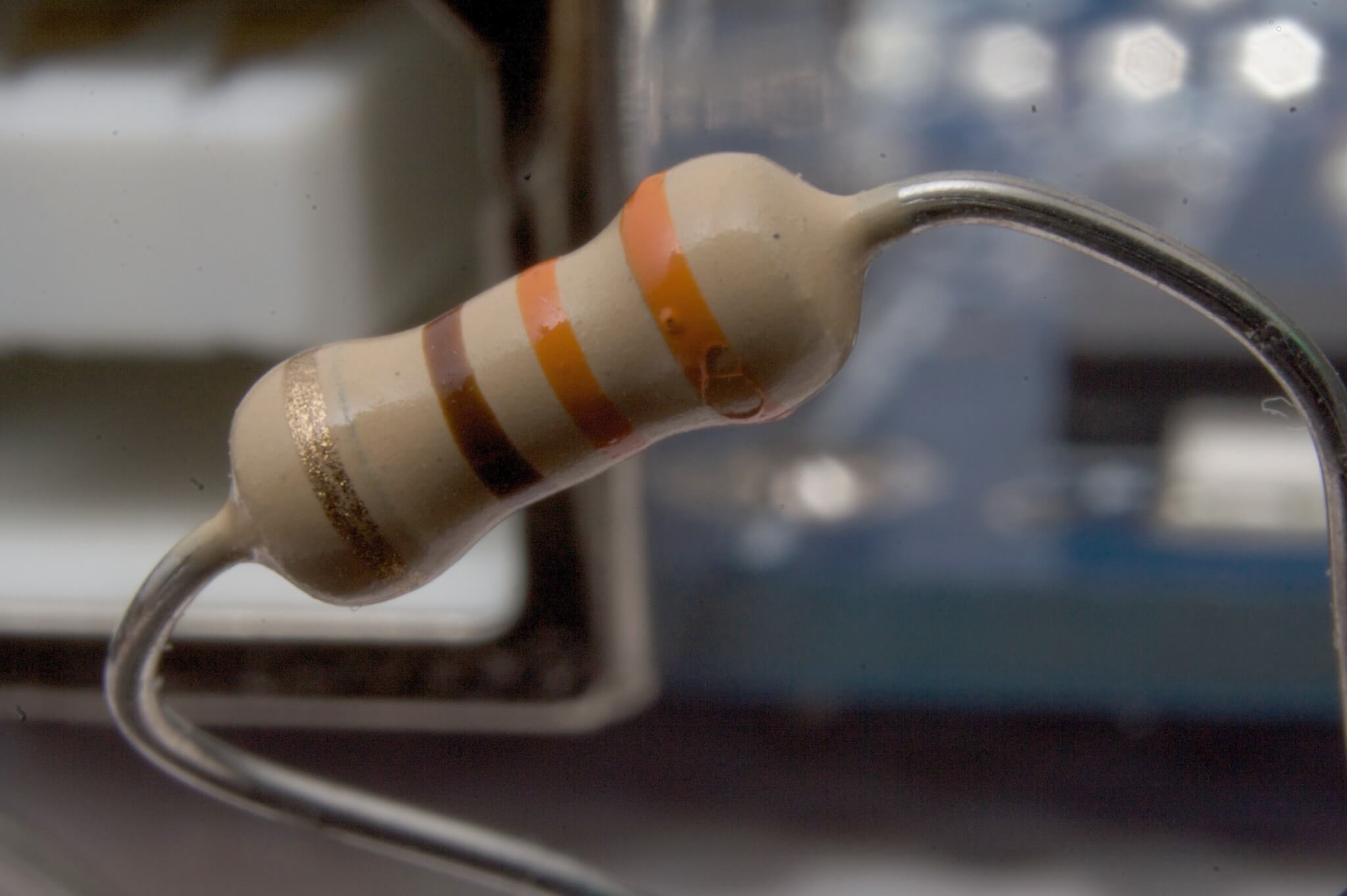
The system of representing the resistor value is known as colour coding. This coding is standardised by the Electronic Industries Association. The table given below shows the numerical value associated with each colour. To determine the value of resistance, colour bands are always read from left to right from the end that has the bands nearer to it.
resistor color codes image
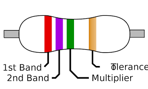
As shown in the diagram below, the first and second band represents the first and second significant digits of the resistance value. The third band is the multiplier represents the number of zeroes that follow the second digit. Sometimes, the third band is of golden or silver colour, then these colours represent a multiplying factor of 0.1 and 0.01 respectively. The fourth band represents the resistors tolerance i.e. the measure of the precision with which the resistor was made by the manufacturer. The silver band represents ±10 % and the gold represents the ±5 % tolerance.
colour code image
Note: If there is no fourth band it shows that the resistor has ± 20% tolerance.

Types of Resistors:

The two main characteristics of each resistor are resistance in ohms & power rating in watts. To obtain a desired current or voltage drop in the circuit, the value of Resistance is perfectly selected. The power rating may be as lower 1/10 Watt to as high as several hundred watts.  From the operating point of view, resistors can be classified as fixed resistors and variable resistors.

(i) Fixed Resistor:

Fixed resistors are those resistors which have fixed value of resistance. These are two types:

(a) Carbon composition Resistors:

It is the most common resistor used in electronic circuits with a low power rating of 2W or less and is made of the mixture of carbon or graphite & clay. For insulation and mechanical strength, the resistor element is enclosed in a plastic case. This type of resistors is readily available in values ranging from 1 Î© to 22MΩ, having a tolerance range of 5 to 20% and power rating of 1/4, 1/2, 1 or 2W. When the wattage of the resistor increases, the relative size of resistors also got increased.

(b) Wire wound Resistor: 

It is an electrical passive component that limits the current. For its construction, a resistance wire made of tungsten, nichrome or manganin etc are wrapped around a hollow porcelain cylindrical core. This whole assembly is coated with an enamel containing powdered glass. To provide mechanical protection to the device, hard and smooth coating is done. The power rating of this resistor is ranging from 2W to 500W and have values ranging from 1 Î© to 100 KΩ.

(ii) Variable Resistor:

In these type of resistors, the value of electrical resistance can be adjusted as per your requirement. To adjust the values of current and voltages these resistors are the best one. These are two types:

(a) Carbon composition Resistors:

In this resistor, a thin carbon coating on pressed paper or a moulded carbon disc constitutes the carbon composition resistance element. These are readily available in values ranging from 1000 Ω to 5 MΩ, approximately having a power rating of usually  1/2 to 2W. A carbon control is often combined with a power on-off switch.

(b) Wire wound Variable Resistor:

In this type of resistor, a resistance wire is wound over a dough shaped the core of bakelite or ceramic. The two ends of the resistance wire are joined to the external soldering lug terminals.


Guest post by  Richard Cappels
If you like this content please comment and support us

Wednesday 14 February 2018

9 easy free Ways Increase YouTube video Views

9 easy free Ways Increase YouTube Video Views

9 easy free Ways Increase YouTube video Views

If the goal of your video is to rack up YouTube views, you have some tough competition. As we often tell our video clients, nonprofits are ultimately competing against cat videos for their audience’s attention.
This means that nonprofit videos need to be entertaining – not just informative. If you can hook your audience with a compelling video, there’s a much greater likelihood that they will visit your website to learn more about your cause or campaign. But you have to pull people in emotionally first – make them laugh, make them cry, or make them think about something in a new and interesting way.
What’s the first step to pulling people in? Your video has to be seen! As the world’s second largest search engine (right after Google), YouTube is a great way to be found. By keeping your audience and their search interests in mind when uploading your video, you can increase the chances people will find it and watch.
Here are 9 ways to increase the views of your organization’s video on YouTube without spending extra money on digital advertising:

  1. Feature it on your YouTube page. Right after you’ve added your video to YouTube, make sure your video the featured video on the front page. People looking at your organization’s YouTube page should be seeing your most current video. It makes your organization look up to date, current and relevant, and puts the video at the center of the YouTube user’s attention.
     
  2. Choose a good thumbnail. If you allow YouTube to automatically choose your thumbnail, it probably won’t be very interesting. Use your computer’s screenshot feature to capture an image from your video that is emotionally compelling, and upload it in your video settings.
     
  3. Make your title short and interesting. Your video title should not necessarily describe your video in a way that makes sense to your administration. Make your title viewer-centric, and think about what would make you want to click on a video. (Upworthy headlines are a good source of inspiration.) And try to keep it brief – a shorter title that doesn’t get cut off is better for click-throughs. Here are a few good title examples from YouTube star PewDiePie for Charity Water and the Sierra Club.
     
  4. Pick tags that will be good for SEO. Your constituents are using YouTube as a search engine – so you should be too! Think about what your supporters are searching, and make sure those keywords are included in your video tags. Keep in mind that what people are searching aren’t always an accurate description of the video.
     
  5. Write a good video description. In your video description, consider telling people a story instead of describing what’s happening in the video. Be entertaining, and remember that the description area is not the place to hit messaging points. PETA does a good job of video description storytelling in their video “Circuses in 60 Seconds Flat.”
     
  6. Take advantage of the nonprofit annotations on YouTube. It’s amazing how many people don’t know about video annotations – we were telling nonprofits how to use them all the way back in 2009! Annotations should come up at least 30 seconds in to your video and right before the end of the video, and should provide a link where people can take action. And don’t forget to check your links to make sure they’re going to the right place!
     
  7. Upload a transcript of your video in English and Spanish. About 38 million people in the United States speak Spanish. By uploading transcripts of your video in both languages, your video will start appearing in English and Spanish YouTube searches. Transcripts alert YouTube of what keywords are featured in your video, and greatly increase the likelihood that your audience will find you via YouTube search.
     
  8. Post early and often. People don’t click on every link that’s posted by on an organization’s social media platforms. Make sure you’re continuing to post your video regularly for at least a month, and keep your posts fresh by changing the headlines and images you feature. This will include your viewership dramatically by increasing exposure to new audiences.
     
  9. Add a lightbox or pop-up on your website. A video is a great opportunities to let people know more about your organization, regardless of why or how people are coming to your website. If you don’t have a lightbox, make sure your video is featured somewhere on the homepage of your site. Negotiate website placement ahead of time, since it can be a space that is coveted by other departments. Your video deserves to be highlighted. It’s new content and your biggest fans would love to see it.

The goal of a video is to be seen. By taking a few small steps, you can dramatically increase the number of people who watch your video and want to engage with your organization, without spending extra money on digital advertising.
Guest Post by Tristan Hanson

How To Make An 8x8 LED Matrix display with arduino | techmodernize

Learn how to make an 8x8 LED matrix controlled by an Arduino.

Scroll down further for step by step photos and more details.
  1. You’ll need the following parts: a prototyping board, (2) 8 pin headers, (8) 200 ohm resistors and (64) red LED bulbs.
  2. Arrange the LEDs in the board according to the design you’ve chosen: either common row anode or common row cathode.
  3. Solder the LEDs to the board, being careful to not to cross any of the anode or cathode leads.
  4. Attach the 8 pin headers to feed power to the LEDs, be sure to place a 200 ohm resistor in line with each positive power lead.
  5. Test your board for continuity with a multimeter.
  6. Attach power to the 8 pin headers.
Today we will be starting our adventure into the deeply complex, yet totally incredible world of LED Matrices. This post is the first of an entire Arduino Matrix Programming series by Circuit Specialists.
First things first, what the heck is an LED matrix, and how does it work??
Simply put, an LED matrix is a grid of lights arranged into rows and columns. LED stands for Light Emitting Diode, so like with other diodes, electricity flows through it in only one direction – from anode(+) to cathode(-); doing so illuminates the light.
By arranging the anodes (positive side) and cathodes (negative side) in a particular way, we can achieve a matrix and call upon each LED individually by sending high and low signals from our arduino device.
Led matrices come in two arrangements. Common-row anode (left) and common-row cathode (right).
8x8 LED Matrix
The difference between these two configurations determine how you would call on a specific LED. With common-row anode (left), the current sources (positive voltage) are attached to rows A – D. Currents sinks (negative voltage, ground) are attached to columns 1 – 4.
Conversely, with common-row cathode (right) the current sinks (negative voltage, ground) are attached to rows A – D and currents sources (positive voltage) runs through columns 1 – 4.
Applying this knowledge, to light the top-right LED (A,4) in a common-row cathode matrix you would feed positive voltage to column 4 and connect row A to ground.
We will be building this arrangement of common-row cathode matrix in this tutorial.
Step 1: The Parts
To build this matrix, we will need a few things to get us started.
1 – Prototyping Board
2 – 8 Pin Headers
8 – 200ohm resistors
64 – Red LEDs
Some other essential supplies include: Soldering ironSolder, Desoldering wire / rosin flux (just in case), wire (we recommend 2 different colors to stay organized), Heat shrink tubing (optional). We also recommend keeping a multimeter close by for testing purposes.
This will get the matrix built, later we will discuss what’s needed to get it running.
Step 2: The LEDs
We’re going to be using a total of 64 5mm Red LEDs, it never hurts to have some extra though. Circuit Specialists stocks a pack of 100 5mm red LEDs you can get for only $1.65.
8x8 LED Matrix
Make sure you note which side is the cathode(-) and the anode(+). Hint: it’s the long side on bulbs from Circuit Specialists.8x8 LED Matrix
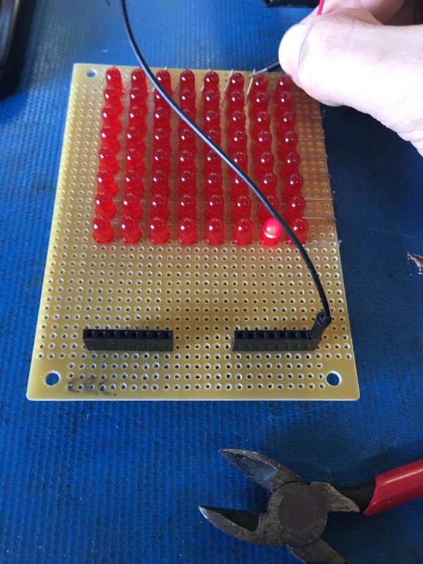
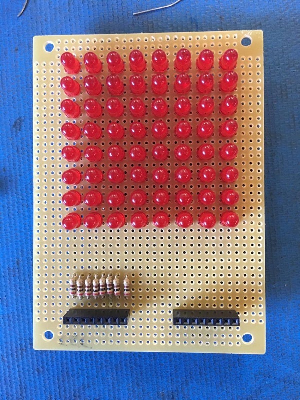
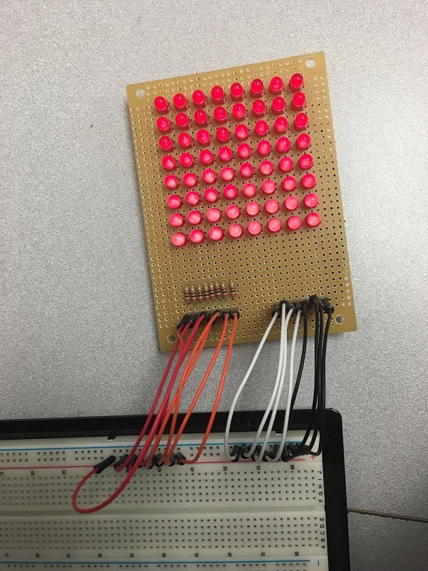
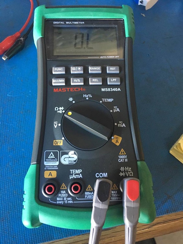
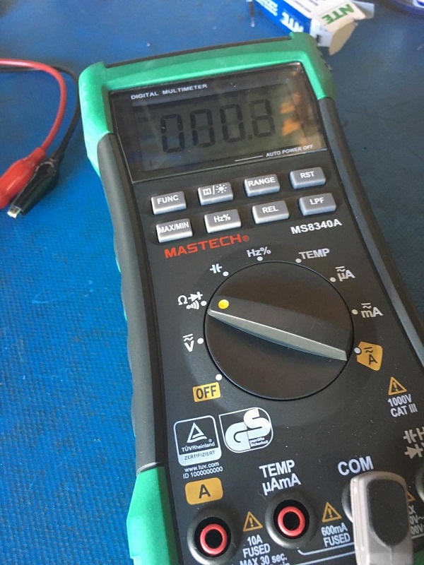
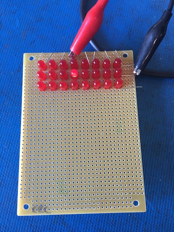
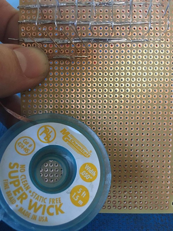
Or, you could always give it a quick test! Make sure you use a resistor!
8x8 LED Matrix
Now, we will begin arranging our bulbs on our perf board. We recommend the 3 x 4-1/4″ Solderable Perf Board model: 64-8934.
8x8 LED Matrix
Step 3: Arranging the LEDs
Because we’ve opted to use the common-row cathode arrangement in our matrix, we will be inserting the pins of the LEDs into the perf board in a particular fashion. It is extremely important to be diligent in this process.
8x8 LED Matrix
As you can see, we’ve opted to keep the long side (anode) on top, because we will be bending them vertically.
8x8 LED Matrix
Now the fun begins….
Step 4: Soldering the Matrix
Our weapon of choice for the soldering portion of this build is the CSI Premier 75w Soldering Station. We will also be taking advantage of the immensely useful ZD10Y Helping Hand System (it makes ALL the difference).
8x8 LED Matrix8x8 LED Matrix
Once we’ve successfully soldered a row of cathodes, we can test their conductivity using a multimeter set to continuity mode.
8x8 LED Matrix
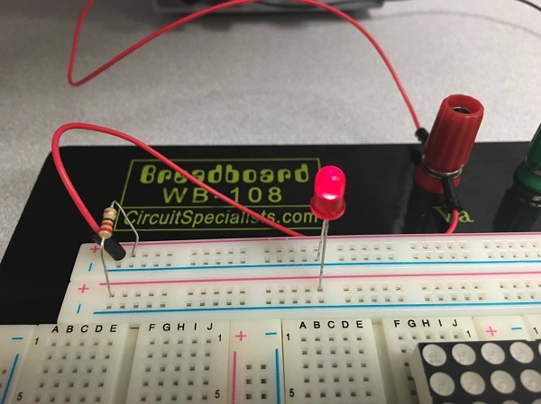
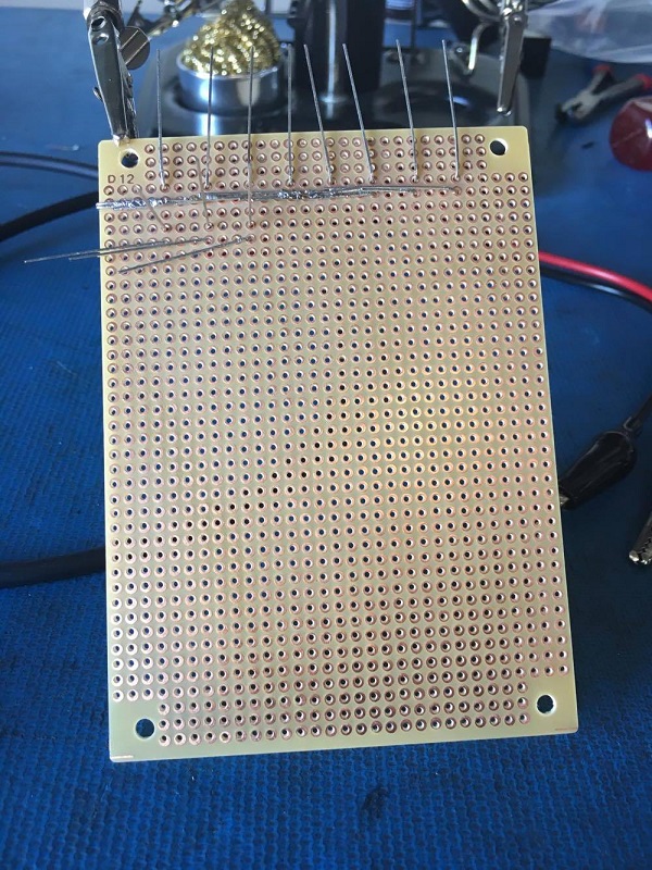
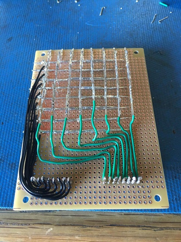
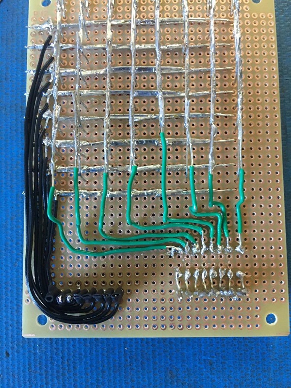
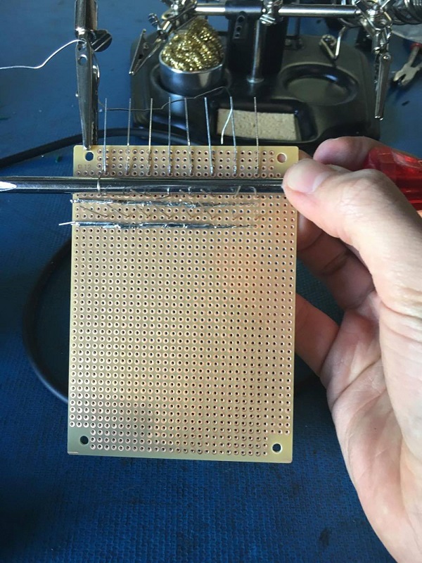
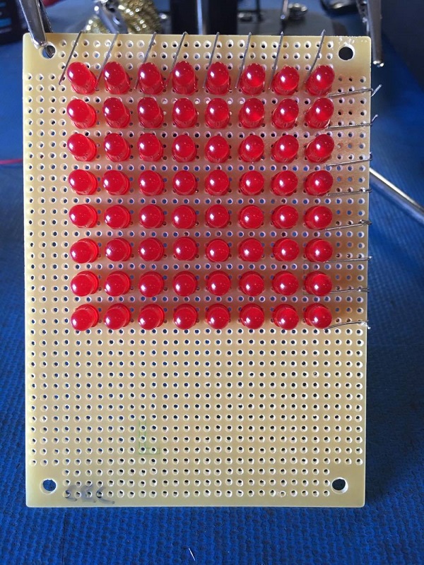
Leads set to each side of the row.8x8 LED Matrix
Any reading besides “OL” means you have a complete circuit.Multimeter Continuity
Checking our work along the way will save a TON of frustration later.
Now, we will start soldering the anode columns. 
It’s absolutely critical that the anodes DO NOT touch the cathodes. Here, we’re using a screwdriver to assist with the bending process.
8x8 LED Matrix8x8 LED Matrix
Now, let’s check our work again. Connect ground to your rows, and power to your columns… make sure you use a resistor!
powered breadboard makes this process extra easy, but any breadboard will do.
8x8 LED Matrix
8x8 LED Matrix8x8 LED Matrix8x8 LED Matrix
This is what will happen if you do not use a resistor (blown bulb)….
8x8 LED Matrix
Another easy mistake you might want to avoid (doh!)….
8x8 LED Matrix
This is why desoldering wire and rosin flux are essential parts of your tool kit!
8x8 LED Matrix
This is what it’ll look like when your soldering is complete.
8x8 LED Matrix8x8 LED Matrix
Step 5: Attaching the connectors
Now that our LEDs are arranged and we’ve tested each of the circuits, we will go ahead and attach the 8 pin headers to the perf board.
8x8 LED Matrix
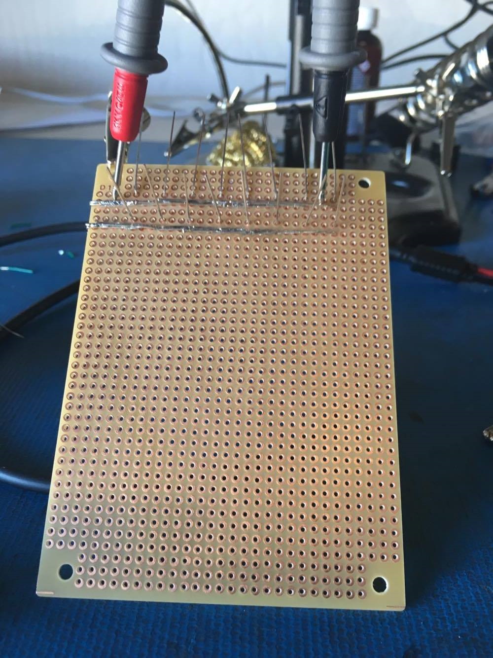
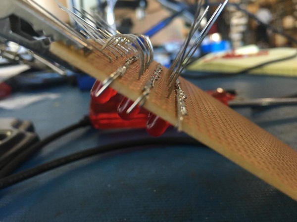
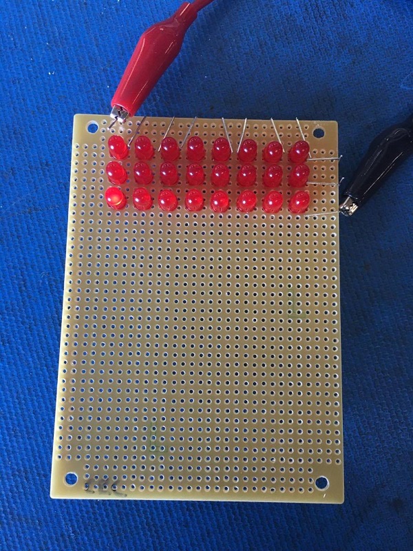
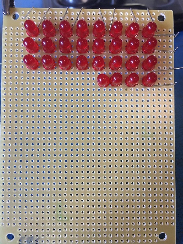
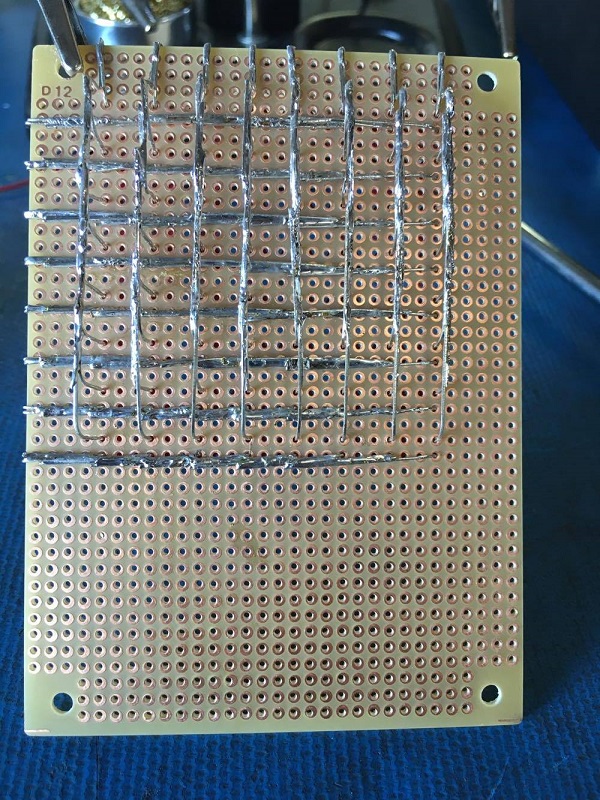
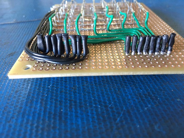
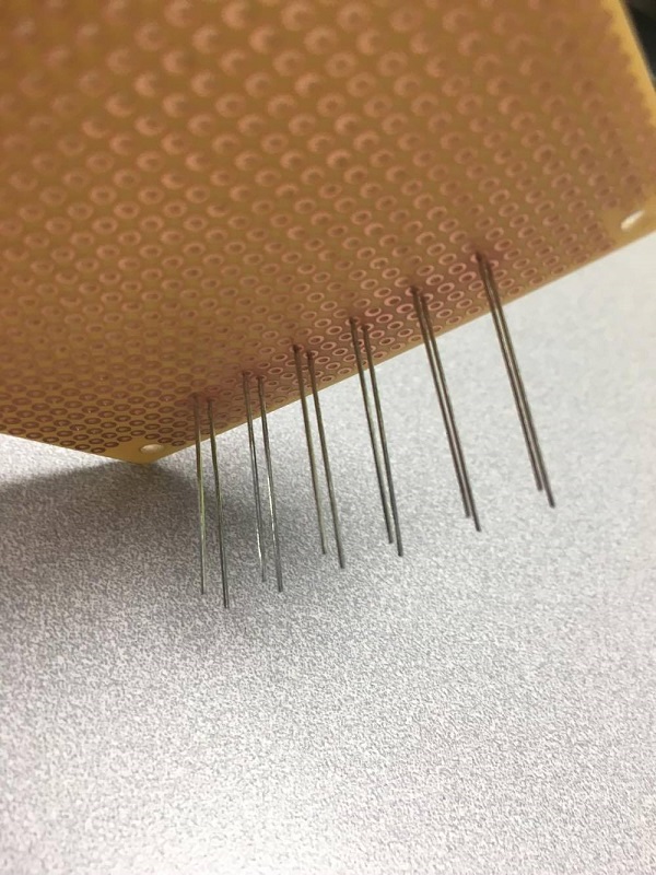
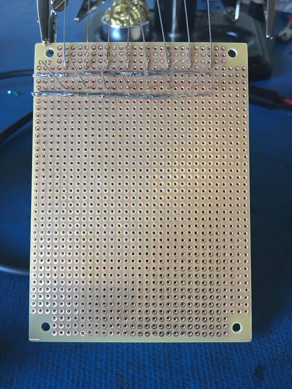
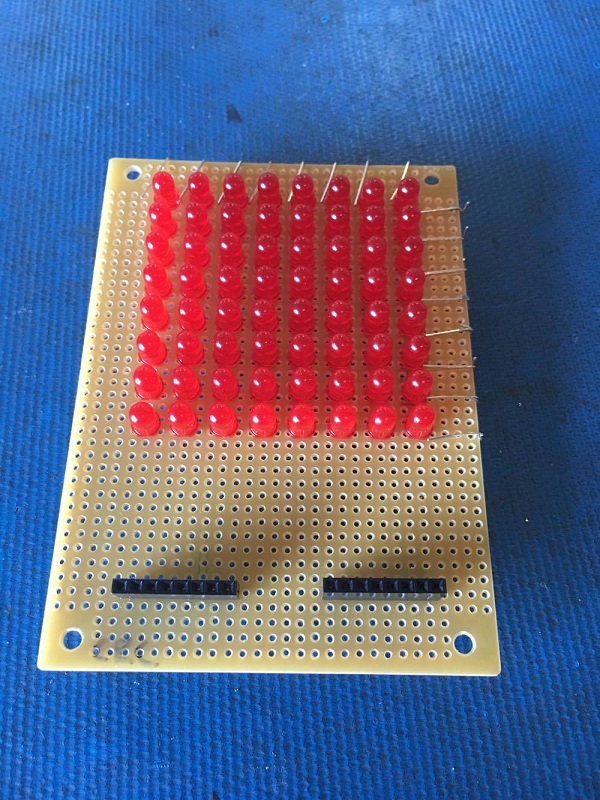
Then we’ll add some solder to keep the headers secure.
8x8 LED Matrix
Now comes the (arguably) most difficult part of this build with regards to soldering skill…. connecting the pins to the rows and columns.
Keep in mind that the pins will be reversed when you flip the board over, so pay close attention to your work.8x8 LED Matrix
8x8 LED Matrix
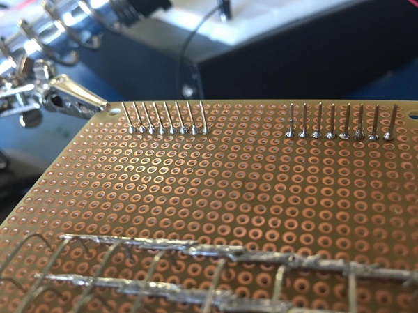
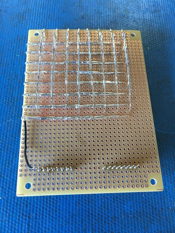
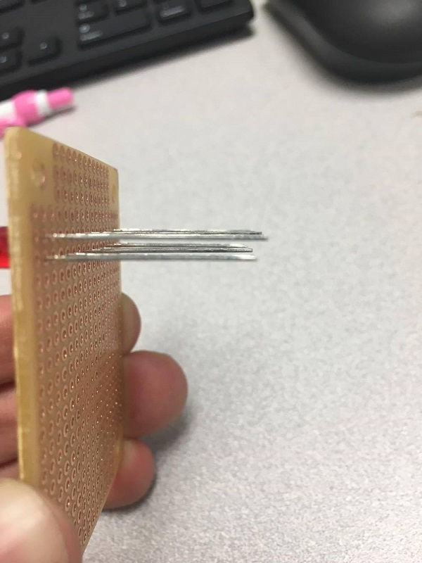
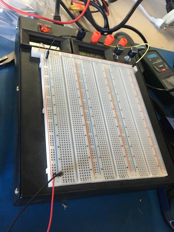
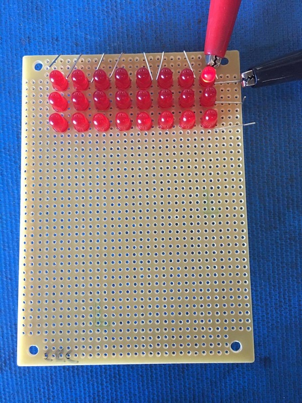
Now we’ll test our connections one by one.
8x8 LED Matrix
Then, we move on to the anode side. 8x8 LED Matrix
Then a little heat shrink to keep everything neat. 8x8 LED Matrix
As you probably noticed, I initially forgot something very important…. THE RESISTORS!!
Try to avoid this, and get them in the power lines from the start.
8x8 LED Matrix8x8 LED Matrix
Okay, much better… now we can power up the unit!
8x8 LED Matrix
Looks great! Now we can start learning how to program the matrix using the OSEPP Uno R3 – Arduino compatible board!
Guest Post by Cody Mack
Please comment and support us!!!!!!!!!!!

Monday 12 February 2018

How capacitor works| Animation and analogy

How Capacitor works? Animation and Analogy


The simplest capacitors are big plates of metal close to each other but not touching. When connected to a potential difference (e.g. a battery), the battery tries to push electrons through the wire away from its negative terminal. Although there isn't a complete circuit, you can imagine that you can shove a few extra electrons onto a big sheet of metal . Let's face it, given the choice between being stuck at a negative terminal or going to a neutral metal plate, electrons will get up and move! So you get a flow of electrons to the plate i.e. you get a current without a complete circuit, but only for a short period of time.

How capacitor works


(Image: Capacitor works)

At the start the capacitor is fully discharged.

When the switch is closed, the capacitor is charged up from the energy stored in the battery until

the capacitor has the same voltage as the battery. At first it charges up rapidly and then gradually

slows.


Open switch. The capacitor remains fully charged.


Pushing the RESET button short circuits the capacitor and the energy stored in the capacitor is now

 discharged, slowly at first. With small capacitors the energy discharge is very fast, almost immediate.

With large capacitors, this can take a long time.

This is why capacitors are used in timing circuits.


Capacitor Analogy 

Think of water flowing through a pipe. If we imagine a capacitor as being a storage tank with an inlet

 and an outlet pipe, it is possible to show approximately how an electronic capacitor works.


First, let's consider the case of a "coupling capacitor" where the capacitor is used to connect

a signal from one part of a circuit to another but without allowing any direct current to flow.


How capacitor works


(Image: Capacitor passes AC in coupling circuits)


If the current flow is alternating between zero and a maximum, our "storage tank" capacitor will

allow the current waves to pass through.


how capacitor works


(Image: Capacitor blocks DC in coupling circuits)


However, if there is a steady current, only the initial short burst will flow until

 the "floating ball valve" closes and stops further flow.


So a coupling capacitor allows "alternating current" to pass through because the ball valve doesn't

get a chance to close as the waves go up and down. However, a steady current quickly fills the tank

so that all flow stops.


Now, lets think about the De-coupling Capacitor


How capacitor works


(Image: Capacitor bypassing the AC in de-coupling circuits)


Where a capacitor is used to decouple a circuit, the effect is to "smooth out ripples".

 Any ripples, waves or pulses of current are passed to ground while d.c. flows smoothly.